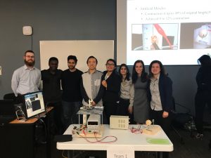
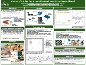
There’s a lot to share on our poster, but that is because there is so much we have accomplished over the last year. We enjoyed sharing and presenting our eye robot at demonstration day! Thank you sincerely to our mentor, Dr. Wei, and our professor, Dr. Ross, for your continuous support. It meant more than you know to us.
Look how far we have come
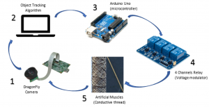
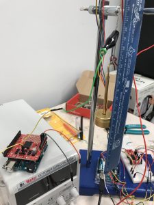
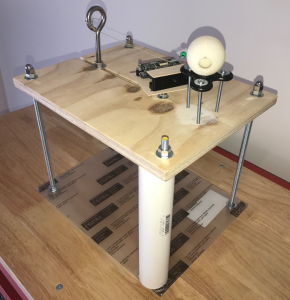
November 16, 2017Over the past semester, we have worked on a number of important steps with our eye model project. Here is an illustration of the design setup:
Construction of the eye model has been a multiphase process. To date, we have replaced the stepper motor with a customized pair of artificial muscles and a 4 Channel Relay Module (for more information please see the Eye Robot Model Description page). By modulating the time of voltage supply, the muscles respond differently and function antagonistically to move the eye to track an object. The system foveates when the camera remains centered on the object.
The steps of the process are listed below:
- Image acquisition
- Object tracking algorithm detects and tracks object
- Arduino receives location of the object from motion tracking algorithm
- Arduino with 4 Channel Relay Module uses muscle characterization function to supply and modulate output voltage to muscles
- Conductive nylon sewing thread used to actuate robot eye and mimic extraocular muscle contraction and relaxation
- Artificial muscles contract when voltage is applied allowing the camera to move and follow an object
- Relay provides voltage when object moving and stops voltage supply when the object is foveated
Muscle Endurance Testing
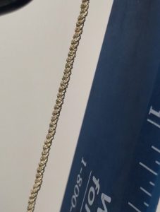
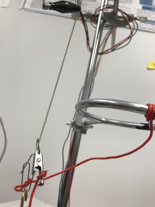
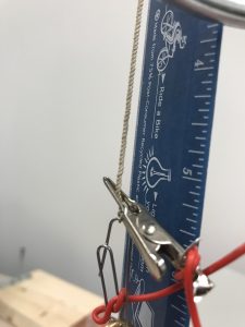
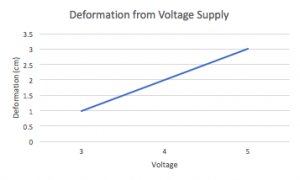
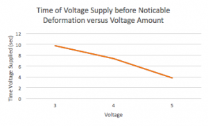
October 21, 2017Endurance testing of the muscles was performed to determine breakdown voltage. The response of the strand from continuous voltage supply. The DC power supply was slowly increased from 0 to 3 V in 9.72 seconds causing the strand to deform 1 cm. The strand was relaxed, then given a supply of 4 V over 7 seconds. At this voltage supply, the strand deformed 2 cm from its original length of 15 cm. The strand was relaxed again and supplied 5 V. The strand deformed 3 cm and snapped after 3.77 seconds. Graph 1 is a trend of the deformation amount (cm) with increasing voltage supply. Graph 2 displays the time in seconds a muscle can withstand a specified voltage. The negative trend demonstrates that at increasing voltage supply, the muscle can endure less time of supply. The muscle used for this test snapped after 10 times of supplied voltage after 5 times at 6 V, and 5 times at 8 V.
Muscle Endurance Testing Images
Graphs
Graph 1: Muscle deformation from voltage supply in centimeters with increasing voltage supply.
Graph 2: Time of voltage supply to muscle strand in seconds with increasing voltage supply.
What have we been up to?
September 17, 2017A lot has happened with the construction of our eye-bot! A fidget spinner will be used as a “frictionless” platform for the eyeball to sit. This is important because the weight of the motion tracking system must not affect the mechanism of contraction of the muscle fibers. On sliding door rolling assembly replacements behind the eye is part of the motion tracking system.
It is important to note the material chosen for the muscles and why. Silver plated nylon, a commercially-available high conductive twisted yarn was chosen for the following reasons [1]:
- reversible–fiber-direction thermal contraction
- large volumetric thermal expansion
- large anisotropy in thermally induced dimension changes
References
[1] C. S. Haines et al., “Artificial muscles from fishing line and sewing thread,” Science (80-. )., vol. 343, no. 6173, pp. 868–872, 2014.
Thanks for visiting us!
April 7, 2017Welcome to the Biologically-Inspired Eye Robot with Artificial Muscles project webpage! We would like to thank Qi Xing, Sunil Kumar Rajendran, and Daniel Boakye for their continuous support throughout this project. We could not have done it without you!